This page is under development. Additional details are pending.
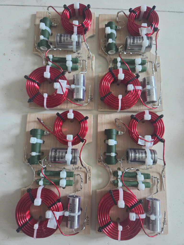
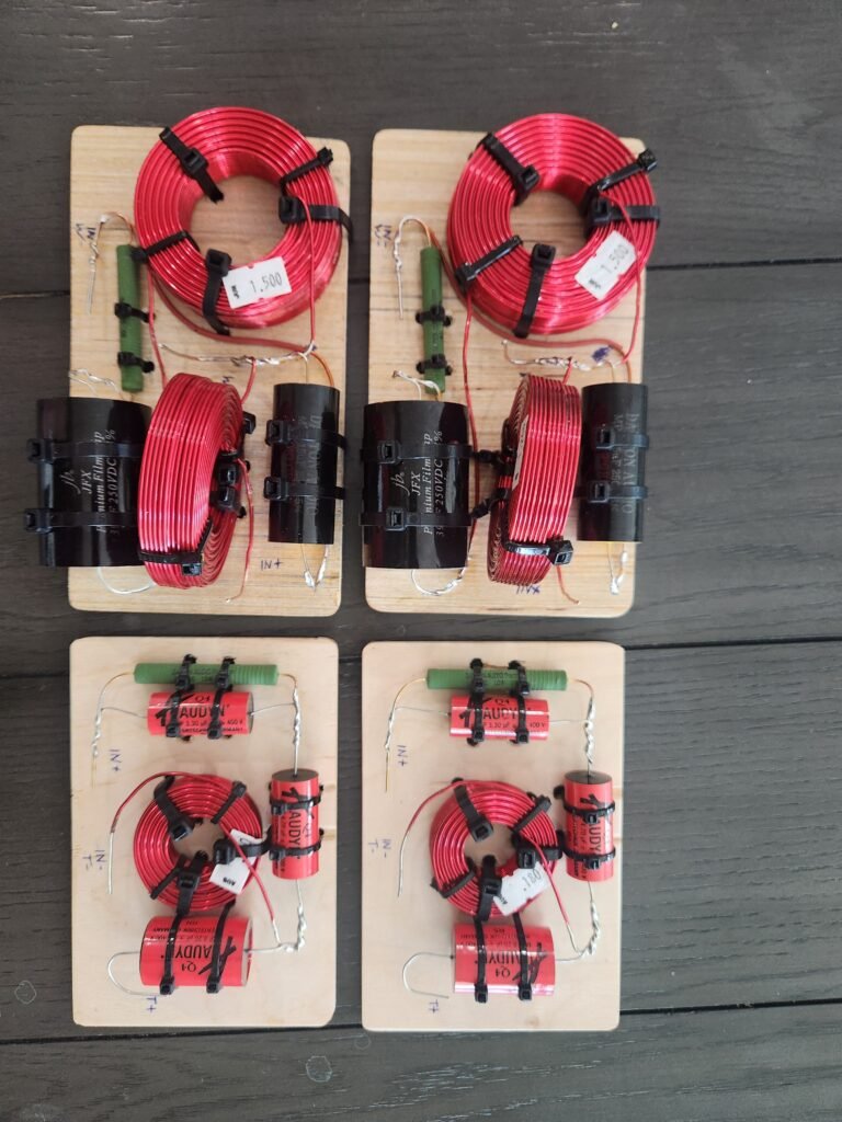
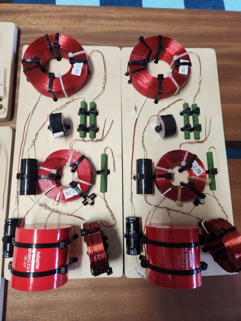
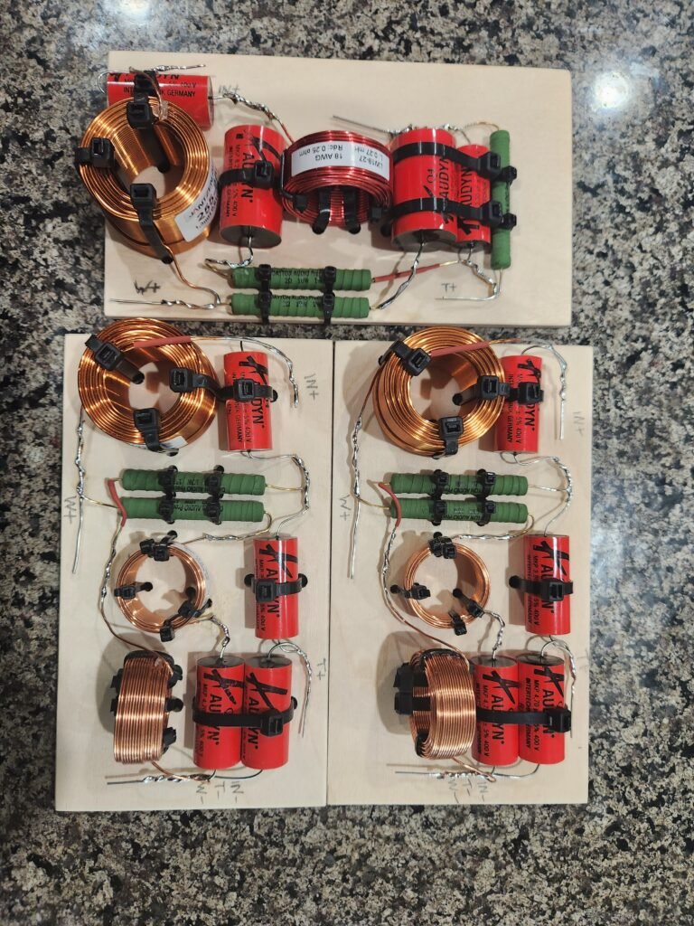
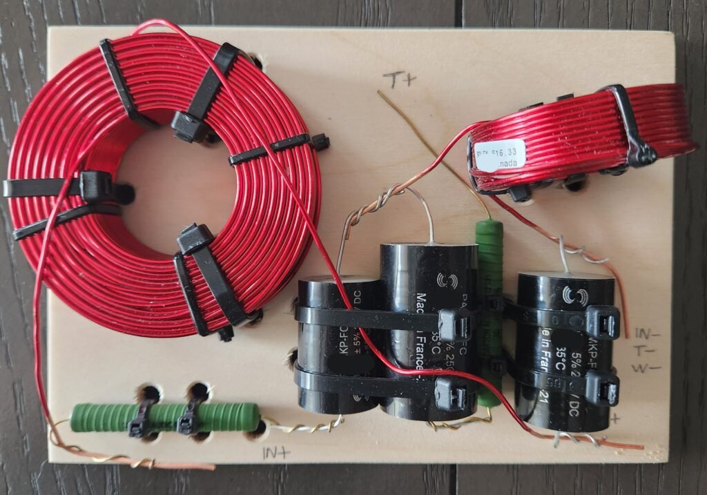
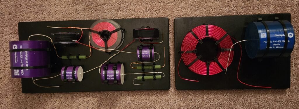
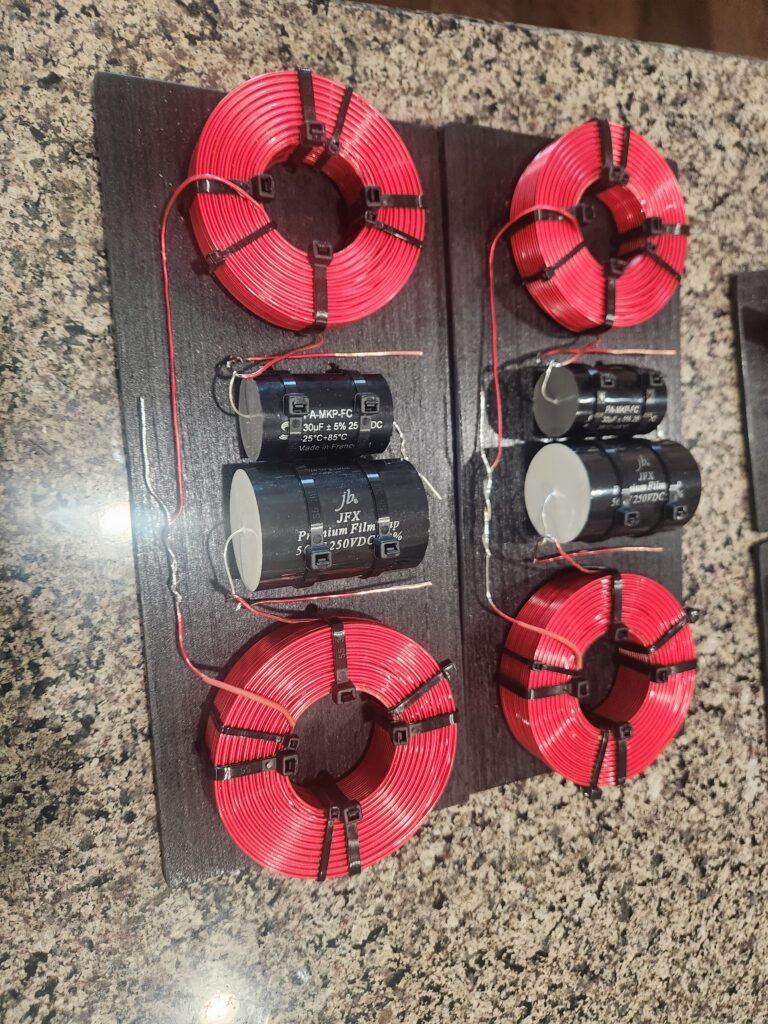
Photos to show assembly methods and layout styles.
FAQ (frequently asked questions)
Q: Do you use PCB boards ? A: No. Point-to-point assembly is used. PCB boards add cost for an inferior connection method. Point-to-point wiring creates a mechanical (twisted) connection at each joint, which when secured with a proper solder joint will not fail under normal use. Additionally, the cumulative wire plus wire solder joint is a heavier gauge connection than the thin trace used in the PCB board. As an example, in point-to-point, a 19 ga resistor lead is combined with an 18ga capacitor lead, for a cumulative 16ga connection across that joint (not including additional conductive mass from the solder). In contrast, the thin copper trace in the PCB board might only be equivalent to a much smaller 19ga or 20ga which is also stretched out over a longer distance.
Related note: PCB boards are very effective for reducing assembly labor in repetitive bulk production. Ultimately, in an individual or custom assembly, the design time and cost associated with creating a custom PCB is greater than the labor for point-to-point wiring. PCB brings no performance gain in this application, and arguably is inferior in its connections and durability.
Q: What type of material do you use for crossover boards? A: Baltic Birch or similar high-quality plywood. Final material selection is influenced by the weight of the crossover components and the size of the board (determined by the size of components, size of woofer openings, and size of the cabinet). The assembly can absolutely accommodate a customer’s special requests (with appropriate material costs added), such as solid or exotic hardwoods, painted boards, acrylic, or other specific materials to accommodate visible or externally mounted applications.
Q: Can the crossover be bi-wired or bi-amped using more than one pair of binding posts? A: Yes. If the design or customer requires multiple input connections they will be provided. The assembly generally follows the original design of the speaker. If the original design includes dual binding posts, the assembled boards will accommodate the same, unless an alternative is requested. If you have any specific request, please communicate it.
Q: Why are some crossovers split onto two separate crossover boards? A: The decision to split onto multiple boards is influenced by the size of components and size of the speaker cabinet and driver openings. Premium aftermarket parts are consistently larger than the cheap OEM components used in most retail speakers. Two smaller boards are easier to place and install into a cabinet than a single larger and heavier board. Many 2.5 way and 3 way designs are more likely to require two boards due to the increased number of parts and the larger-sized inductors used in the low-pass filters of dedicated bass circuits.
Q: Will the connections to the assembled crossovers be labeled? A: Yes, connection points to the input terminals and to each of the driver terminals are labeled for your convenience and future reference.
Q: What is your recommended method for attaching the internal wiring to the crossover? A: A simple soldered connection is recommended. Solder the internal wire to the crossover lead. Place a small piece of heatshrink over that connection, and secure it to the crossover board with a zip-tie or adhesive. The addition of screw down terminals, internal binding posts, or other additional connection devices on the crossover board is not our default recommendation. It adds unnecessary additional cost and takes up additional space, while offering an inferior connection. Many of the commonly used terminals are made from steel or brass, which are inferior conductors to copper. If soldering is completely out of your comfort and you choose to use terminals or other wire joining tabs, please avoid steel, and select brass options as a minimum if copper terminals are not readily available. If you have a special request, please send us an email and I will go out of my way to support your project.
Q: Where in the cabinet should the assembled crossover be installed? A: Your best access point is through the largest driver opening, and any accessible surface is acceptable. With smaller 2-way bookshelf designs, the floor of the cabinet may be accessible and ideal. With taller cabinets or some cramped designs with a low-mounted port, the floor may not be accessible. Side walls or the rear wall above the binding posts are all acceptable options. Whenever you are mounting on a vertical surface, consider supporting the bottom edge of the crossover to eliminate lateral weight stress on your mounting screws. That support can be the floor of the cabinet, a horizontal support, or you may glue a small scrap piece of wood to the cabinet to serve as a support. It is important to pre-drill your cabinet at the mounting screw locations, especially with MDF cabinets. Mounting screws for the crossover boards can be placed anywhere on the crossover board. Screws don’t need to be placed symmetrically in the corners. The only location on the board to avoid would be a screw placement through the center of an aircore inductor (magnetic field). Access within a small cabinet space may limit and restrict where screws are placed, so just be flexible. In some unique cases where there is no access to drill or install screws, an appropriate adhesive can be used.
Q: Does your basic crossover assembly service include attachment of internal wiring? A: No, assembled crossovers as a default do not have internal wiring already attached, but that servie can be provided. Attachment of internal wiring is recommended to be completed by the speaker owner. Having the speaker cabinet in front of you while temporarily placing the crossover inside or next to the cabinet allows you to most easily and accurately estimate the lengths needed for each wire connection. Small elements such as cabinet bracing or internal port tubes can significantly impact crossover placement and therefore change the lengths of wire needed for each connection. This may not be as significant with a small bookshelf design, but the differences can be very significant in a tower or larger format design. For that reason, your connection of the wires based upon your selected crossover placement is the most efficient.
You may request that I attach the internal wiring as an add-on to your crossover assembly. With that request, I will use the published cabinet dimensions to estimate wire lengths, based upon likely crossover mounting positions. To ensure your successful install, I am required to over-estimate wire lengths and ensure that each wire connection has sufficient length for flexible and easy installation. I do charge a small fee for this additional time and service of estimating and measuring each wire length based upon the speaker dimensions and layout, and making the final connections. It is generally a 1.5 to 2.5 hour task.